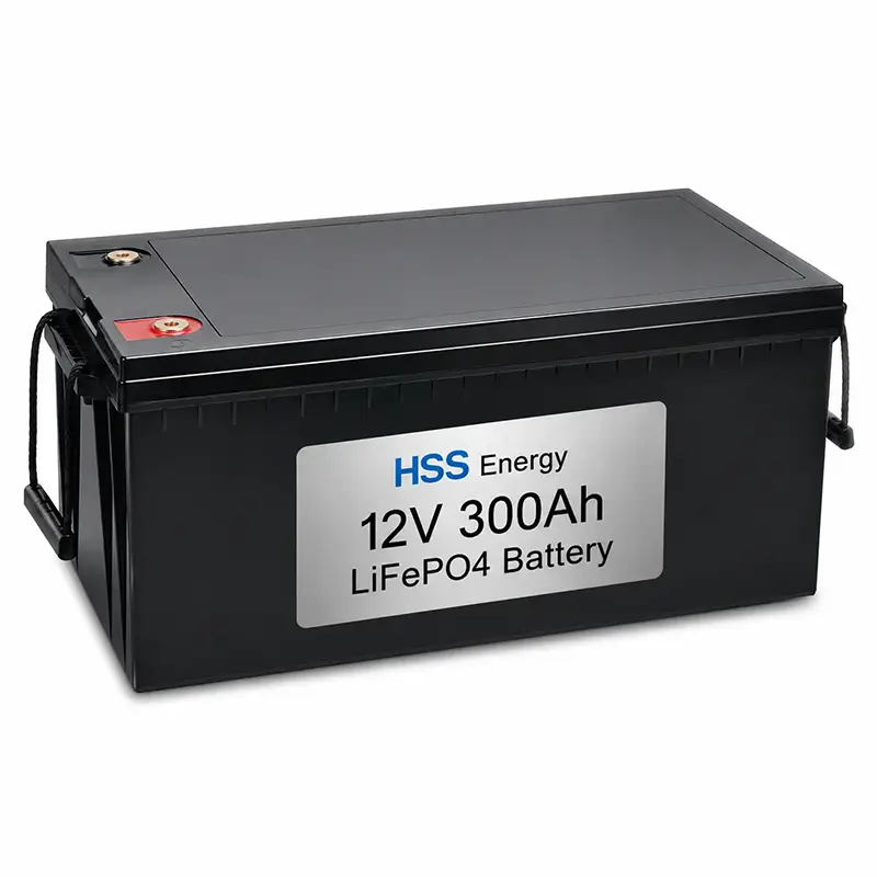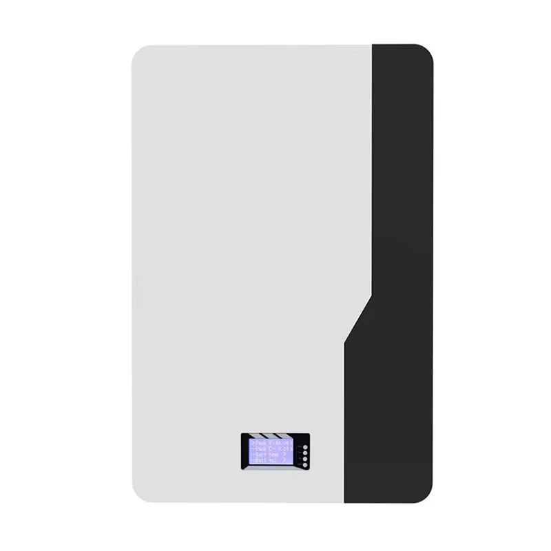
An AGV or mobile robot battery has to do more than meet a voltage and capacity target. Runtime, acceleration current, charging windows, battery-bay dimensions, communication with the vehicle controller and the operating schedule all affect the final pack design. HSS Energy develops project-based lithium battery systems for AGVs, AMRs and mobile robotic equipment, with electrical, mechanical and communication parameters confirmed against the application.
|
Application Focus |
Battery Chemistry |
Charging |
Integration |
|
AGV / AMR / mobile robotics |
LiFePO4 reference platform |
Manual / dock / opportunity charging by project |
CAN / RS485 and project-defined interfaces |
Two AGVs using the same nominal voltage can require very different battery packs. A light warehouse AMR may operate at moderate current for long periods, while a transport AGV can have short high-current events during acceleration, lifting or slope operation. The battery therefore needs to be defined from the duty cycle.
|
Engineering Input |
What It Determines |
|
Vehicle operating voltage |
Series configuration and charger voltage |
|
Average load and operating hours |
Required usable energy and runtime |
|
Peak load and peak duration |
BMS, cell, cable and connector current capability |
|
Battery bay / mounting space |
Enclosure size, terminal position and mechanical layout |
|
Charging window |
Charge current and charging strategy |
|
Vehicle controller |
Communication protocol and signal mapping |
|
Operating environment |
Temperature, enclosure and protection requirements |
The following configuration is based on the supplied HSS reference data. Parameters that are not fixed in the source material remain project-confirmed rather than being assigned generic values.
|
Parameter |
HSS Reference Configuration / Project Confirmation |
|
Market Voltage Class |
24V-class |
|
Nominal Voltage |
25.6V |
|
Configuration |
8S LiFePO4 |
|
Capacity |
60Ah |
|
Nominal Energy |
1.536kWh |
|
Upper Charge Reference |
29.2V (8 × 3.65V); final charger profile project-confirmed |
|
Charge Method |
CC-CV; manual / dock / opportunity charging by project |
|
Continuous / Peak Current |
Project-confirmed from AGV load and peak duration |
|
Communication |
CAN / RS485 project-selectable; mapping confirmed by project |
|
Enclosure / Weight |
Project-confirmed after battery-bay review |
|
Connector / Pinout |
Project-configured |
Capacity alone does not define whether an AGV can complete a shift. Energy requirement should be estimated from the real operating cycle, including travel, idle time, acceleration, lifting or tooling loads and charging opportunities. Peak current should be checked separately from average energy consumption.
|
Sizing Question |
Engineering Check |
|
How long must the AGV operate between charges? |
Estimate usable energy from the duty cycle rather than nominal capacity alone |
|
What is the normal running current? |
Check thermal load and continuous discharge requirement |
|
What is the highest short-duration current? |
Confirm cell, BMS, cable and connector capability |
|
How long does the peak last? |
Distinguish short acceleration peaks from sustained high load |
|
Can the AGV charge during breaks? |
Opportunity charging may reduce the required onboard energy |
|
How much reserve is required? |
Set SOC operating window according to route and charging reliability |
Charging strategy is part of the battery design. The supplied 24V-class reference supports a CC-CV charging approach, while the physical charging method is selected by project. Depending on the AGV system, charging can be manual, dock-based or arranged as opportunity charging during scheduled stops.
· Manual charging: suitable where vehicles can be taken out of service for a defined charging period.
· Dock charging: charging interfaces and control logic are matched to the docking arrangement.
· Opportunity charging: short charging periods can be incorporated into the operating schedule where the charger, battery and route strategy support it.
· Final charge current, connector/contact design and control signals must be confirmed with the charging equipment and vehicle controller.
For AGV and robotics projects, the BMS is not only a protection device. It can also provide operating information to the vehicle controller. The supplied reference supports project-selectable CAN or RS485 communication, with protocol mapping confirmed for the project.
|
BMS / Interface Item |
Project Role |
|
Voltage, current and temperature monitoring |
Battery operating status and protection input |
|
Overcharge / over-discharge protection |
Prevents operation outside configured battery limits |
|
Over-current / short-circuit protection |
Responds to abnormal electrical conditions |
|
Temperature protection |
Controls operation when temperature exceeds configured limits |
|
SOC data |
Supports remaining-energy indication and charging decisions where implemented |
|
CAN / RS485 |
Vehicle/BMS communication according to the confirmed protocol |
|
Protocol mapping |
Signal definitions and communication behavior confirmed with the customer |
AGV batteries are frequently constrained by an existing battery bay. Enclosure dimensions, handle position, cable exit, connector location and service access should therefore be reviewed before the mechanical design is frozen. The supplied reference leaves enclosure, weight, connector and pinout open for project confirmation.
· Battery-bay dimensions and mounting points
· Metal or other project-appropriate enclosure construction
· Connector and cable selection according to current and vehicle interface
· Terminal / connector position and cable exit direction
· Display or status interface where required
· Service access, lifting and replacement requirements
· Project-specific label and identification
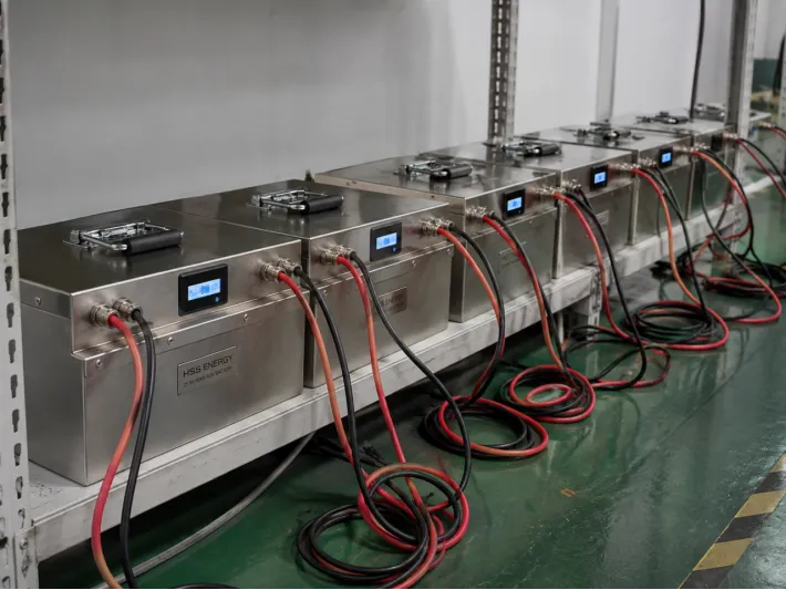
HSS Energy AGV battery units during batch electrical verification
For a custom AGV battery, production control has to confirm both pack consistency and the interfaces that matter to the vehicle. Verification is defined against the approved project specification rather than a single generic checklist.
· Battery voltage and electrical inspection
· BMS functional and protection checks
· Charge/discharge verification according to the approved configuration
· Communication check where CAN or RS485 is specified
· Connector, cable and pinout inspection
· Display/status check where fitted
· Mechanical and appearance inspection
· Project-specific final inspection before shipment
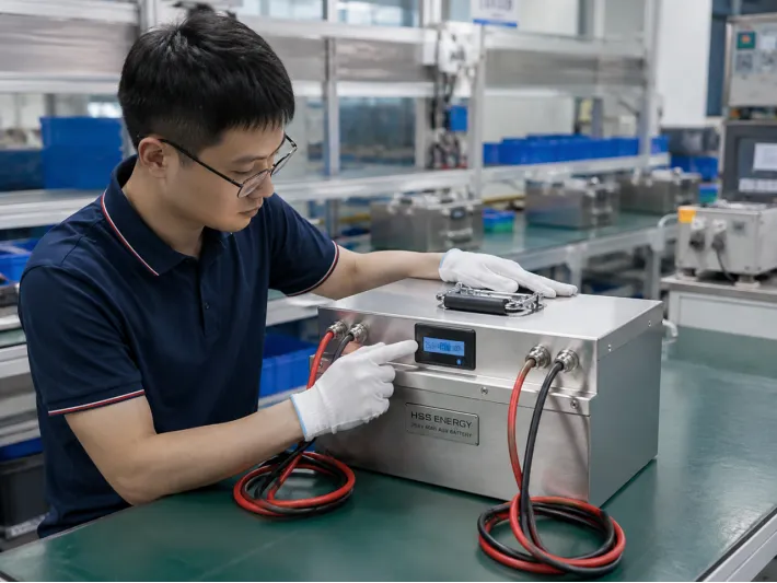
Final functional inspection of an HSS Energy AGV battery assembly
|
Application |
Battery Design Focus |
|
Warehouse AGV |
Runtime, route cycle, docking and vehicle communication |
|
AMR |
Compact integration, SOC information and frequent charge opportunities |
|
Material-Handling Robot |
Peak current during acceleration and payload movement |
|
Autonomous Cart / Tugger |
Long operating hours and repeatable charging schedule |
|
Inspection Robot |
Compact packaging and application-specific runtime |
|
Service / Mobile Robot |
Mechanical integration, low-voltage platform and communication needs |
|
Step |
Stage |
Output |
|
1 |
Vehicle Data |
Voltage, load, runtime, battery bay, charger and controller |
|
2 |
Battery Proposal |
Chemistry, series configuration, capacity and electrical architecture |
|
3 |
Interface Confirmation |
Connector, pinout, CAN/RS485 mapping and charging interface |
|
4 |
Sample |
Prototype pack built to the agreed configuration |
|
5 |
Vehicle Test |
Runtime, peak-load behavior, charging and communication checked on the target equipment |
|
6 |
Confirmation |
Specification and interfaces frozen after validation |
|
7 |
Production |
Batch production and project-specific inspection |
|
Question |
If Yes / Required |
Next Check |
|
Existing AGV voltage platform? |
Use the vehicle voltage as the starting point |
Confirm charger and controller voltage range |
|
Full-shift operation without charging? |
Size for required usable runtime |
Check average load and reserve SOC |
|
Charging stops available? |
Evaluate dock or opportunity charging |
Confirm allowable charge current and contact/interface design |
|
High acceleration / lift load? |
Treat peak current separately |
Confirm peak amplitude and duration |
|
Vehicle communication required? |
Select CAN or RS485 as applicable |
Confirm protocol and signal mapping |
|
Fixed battery bay? |
Mechanical design follows available space |
Confirm enclosure, connector and service access |
Certification and transport documentation are configuration-specific. Available documentation should be confirmed against the final battery model, destination market and customer requirement. HSS Energy can provide the applicable documentation package for the approved project where available.
Because AGV and robotics batteries are customized around the target equipment, certification scope should not be assumed to cover every voltage, capacity, enclosure or interface variant unless that exact configuration is included in the relevant certificate or report.
· AGV / AMR / robot type and application
· Nominal system voltage and allowable voltage range
· Average operating current or power
· Peak current and peak duration
· Required runtime between charges
· Daily operating hours / shift pattern
· Battery-bay dimensions and mounting constraints
· Existing battery details, if replacing a current pack
· Charging method and charger specification
· CAN / RS485 requirement and protocol documentation
· Connector, pinout and cable requirements
· Operating temperature and installation environment
· Target market, certification requirement and estimated quantity
The 25.6V 60Ah / 1.536kWh configuration shown on this page is an HSS reference configuration based on the supplied project data. It is not a universal AGV battery specification. Continuous current, peak current, enclosure, weight, connector, pinout, communication mapping and final charger profile remain project-confirmed.
Final battery voltage range, capacity, current limits, BMS settings, communication protocol, mechanical structure, connector system, charging parameters and documentation are subject to the approved project datasheet, technical agreement, sample confirmation, PI or contract. Where website information differs from an approved project document, the approved project document shall prevail.
Send the vehicle voltage, load data, required runtime, peak current, battery-bay dimensions, charging method and communication requirement. HSS Energy can use these inputs to define the battery architecture and the interfaces that need to be validated on the target equipment.